
Measuring and notes
Tape measure, ruler and framing square, distances to the origin, notes that stay attached to a part, and reference points that things snap to.
To build a part exactly, you need to measure. layerling has several tools for that. None of them ends up in an export. Wall thickness and gaps inside a part are best measured in the section view with “Measure”.
The tape measure
The tape measure sits at the lower end of the camera bar on the left edge (“Tape measure”). It measures distances between corners, edges and faces. A click on it opens five buttons. If they cover what you want to measure, drag them by the grip on the left anywhere on the workplane; a double-click on the grip puts them back:
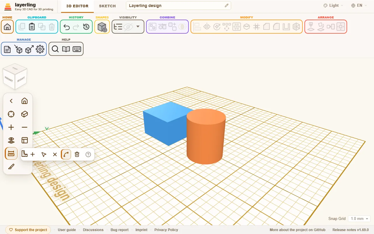
- “Add measurement”: Click one point, drag to the next and click it. The distance is labelled.
- “Move measurement points”: Grab the points and move them, the number follows.
- “Delete measurement part”: Afterwards click a measurement to remove it.
- “Measure whole edges”: A click on an edge measures all of it, the length of a circle for example. With this switched off, a click puts a point on the edge instead, and the second point goes anywhere, so you can measure the diameter or any other distance. Alt turns the switch round for one click. On a circle, the point across from the first one snaps in when the pointer comes near, and the points sit on the true circle, so the diameter comes out exact.
- “Delete all measurements”: Removes every measurement at once. Because this cannot be undone, layerling asks first; with no measurements there is nothing to do.
- “Mark the middle as a reference point”: Under the number of every measurement sits a small crosshair button. It puts a reference point in the middle of the measurement: after a click on a round edge, such as the rim of a hole, in the centre of that circle - on an imported mesh too, where nothing else marks the middle of a hole - and for a diameter or any straight measurement halfway along it. A shape you drag then snaps to the point with its centre. A point that is there already is not made twice.
Esc leaves measuring mode.
The ruler
You fetch the “Ruler” from the shape library. It is purely a measuring tool: it appears in no export and can neither be grouped nor cut. For every body that touches or overlaps the ruler, it shows the extent as a floating number right in the view. You can change that number right there, and the body follows. The floating plus symbol creates a copy of the measured shape.
The framing square
Sometimes you measure better at a right angle. Click “Place framing square” in the camera bar and then the workplane. A framing square with two arms at a right angle, with tick marks like a try square, is placed there. It has no body of its own either. Click close to the corner of a body, and its corner snaps exactly there.
The framing square lies on the workplane. If that sits on the side of a body, the square lies on that side too, see View and workplane. That is how you dimension on a vertical wall: put the workplane on the wall, place the square at its top left corner and click the handle until the arms point right and down.
- Dragging the handle moves it.
- A short click on the handle turns it by 90°.
- The × beside it removes it.
- The small button left of the handle switches what is measured from: the outside of a body (endpoint, an icon with lines) or its middle (midpoint, a crosshair).
If bodies stand at one of the arms, the framing square shows their dimensions automatically. That works on the base plate only, not on the side of a body.
When you select a body, the framing square shows in green how far it is from the corner, along both arms and in height. Click a green number to type a distance, and the body moves exactly there. With several bodies selected, they count as one: the ruler measures their shared outline, and a typed value moves them all together without changing their positions relative to each other.
With the midpoint, the green numbers count to the middle of the body, in height as well. That way you place a sphere with its centre exactly 15 mm from an edge, without subtracting the radius. On a wall you place a hole 40 mm from the left and 190 mm from the top like this: select the hole, switch to midpoint, type 40 and 190. The height there counts outward from the wall.
Both the tape measure and the framing square stay where they are while you sketch and come back to the 3D view. They are not saved with the design and not in the history, and they go when you reload the page.
Distances to the origin and while moving
In the settings under “Appearance” there are two switches for live dimensions:
- “Show movement dimensions” shows by how much you move while dragging.
- “Show origin distances” shows the distances of the selection to the origin of the plate, also with several selected bodies.
With “Dimensions always visible” the dimensions stay visible permanently.
Notes
A note records what the geometry does not say: "This screw is 0.3 mm too tight", "print the lid yet", "dimension from Peter". Place one with “Note” or the N key.
- If you place the note on a body, it travels with it.
- If you place it beside, it stays on the workplane (“On the workplane”).
- “Release from object” releases an attached note from the body.
- Dragging moves the note, a click opens it for editing.
- While you write, Enter keeps the text and Esc puts it back to how it was before you started; Shift+Enter starts a new line.
Notes are saved in the design, appear in no export and can be shown or hidden with “Show notes and points”.
Reference points
A reference point is a bare mark in space, like a pencil mark or a layout point in a workshop: it belongs to no body, is never printed, and other things snap to it. Right-click a body and choose “Mark the centre”, “Mark the corners” or “Mark the edge middles”: the points appear on the top face of the body (of the whole selection, if you selected several).
- Drag a point to move it, or click it to see its coordinates and type new ones; they use the unit you set. Each card can be dragged away by its title if it covers something, on its own: the others stay where they are, and a double-click on the title puts it back. The card you touched last stands in front of the others. Delete all in a card, or in the right-click menu, deletes every point at once. “Delete” removes it.
- The tape measure can mark a point too: “Mark the middle as a reference point”, the crosshair button under a measurement, puts one in its middle, in the centre of a round hole for example.
- When you drag a shape, its edges and its centre snap to a point, like they snap to other shapes (“Snap to other shapes while moving”). The framing square snaps to points too.
- Points are saved in the design, appear in no export, and are shown or hidden together with the notes by “Show notes and points”.
- An AI can mark, list and remove them with
layerling_add_reference_points,layerling_list_reference_pointsandlayerling_remove_reference_points.