
Sketches: from outline to body
Draw a flat outline, round or chamfer its corners and pull or spin it into a body.
Not everything can be put together from basic shapes. For parts with a contour of their own, such as a bracket, a tooth profile or a vase, you first draw the outline and then make a body from it. That is what sketch mode is for.
Starting a sketch
At the top, switch from “3D editor” to “Sketch”. Click “Sketch to 3D” in the ribbon and choose what the outline should become:
- “Extrude sketch”: The outline is pulled upward, like a cookie cutter.
- “Revolve sketch”: The outline is spun about an axis, as on a lathe. That gives vases, cups, cones and everything round.
The editor then shows a sheet with a grid. That is your drawing surface.
Drawing
The ribbon in sketch mode is divided into areas:
- Draw: “Line” makes straight sections: click points one after another; holding Shift snaps the new line in 15° steps, horizontal and vertical included. The length and angle of the new line show at the pointer. You can also type how long it should be, see Lines by numbers. The “Bezier Curve” is shaped with its handles: click a point and drag in the direction the line should carry on, as with the pen tool in Illustrator or Inkscape. The further you drag, the more it bends; the stretch to the new point bends along while you drag, so you see what you get. Dragging while you place a point bends the curve; if you come from Tinkercad and just want to click points, take the “Smooth Curve”. The “Smooth Curve” lays a flowing path through the points you click. To close the outline, click the first point again at the end.
- Shapes: “Add sketch shape” offers ready-made outlines: “Rectangle”, “Circle”, “Oval”, “Half circle”, “Pie slice”, “Bolt circle” (a disc with holes), “Triangle”, “Hexagon”, a “Polygon” and a “Star”. Click one to put it at the origin of the sketch, or drag it from the menu to where you want it. At the bottom of the menu, “Sides / points” sets the number of sides of the polygon and of points of the star, and “Star inner size” how deep the star's valleys reach in towards the middle (10 to 90 percent of the outer radius); both apply to the next shape you add. Like every sketch shape they are ordinary corner points afterwards, so you can move, round or chamfer them one by one.
- Overlapping: Push two closed outlines over each other and they stay two bodies, which merge in the 3D editor; the overlap is not a hole. A hole only comes from an outline lying wholly inside another. Moving does not join the lines where they cross, so you can pull the shapes apart again. If you draw a line across others, though, layerling puts a point at every crossing.
- Selection: “Select” moves points and lines. A click inside a closed outline selects the whole outline, so you can drag or resize it straight away; inside a hole it picks the hole. The frame around the selection has eight handles: the corners change width and height together, keeping the proportions while you hold Shift. The ones on the sides change one direction only. The round handle above the frame turns the whole selection about its middle: the figure over it shows the angle, and with Shift held it moves in steps of 15°. R turns a whole closed outline by 45° at each press. Click the width or height pill to type a new size, also as a sum ("60+12.5") or in percent ("150%"). With Shift held, a click on a point or line adds it to the selection or takes it away again, so you can pick several and move them together. Drag a box over empty space to select everything in it. A line can be dragged too (it moves by its two ends, or all of the selection if it is part of one). The arrow keys move the selection by one grid step, Shift with them by a larger one, and Shift held while you drag keeps the move on one axis. “Add or Remove Points”: a click on a section adds a point, a click on a point removes it. Also there are “Erase” and inserting a template image (“Add Image”).
- Clipboard: “Copy”, “Paste”, “Duplicate” and “Delete” work on the selected points, lines and images, as in the 3D editor; Ctrl+X cuts. Pasted and duplicated geometry lands next to the original with a 10 mm gap, on a free spot where it touches no existing line, so it never gets joined to what is already there. It stays selected, so you can drag it straight into place.
- History: “Sketch undo” and “Sketch redo”.
- View: Pan it with the middle mouse button or with Shift or Ctrl plus the right mouse button, as in the 3D editor. F fits the whole sketch in the view, Shift+F zooms to the selection, and + and − zoom in and out, as in the 3D editor. The “Tape measure” on the side bar measures the distance between two points. The sketch also shows dimensions as soon as you click something: the length of a line, or for a point the lengths of the lines that meet there. The “Show measurements” button on the side bar hides and shows these dimensions when they get in the way, for example while shaping curves; the tape measure keeps working. On a straight line you can click the dimension pill and type the length in millimetres; Enter applies it, Esc cancels. The line keeps its direction, its start point stays where it is, and the lines at the other end follow. With an end point selected, that one moves. Alt+Enter grows the line to both sides around its middle. On curves the pill only shows the length.
A body comes only from a closed outline.
Lines by numbers
Once you have set the first point with “Line” or “Smooth Curve”, just type a number: two fields open next to the line, “Length” in millimetres and “Angle” in degrees. < or Tab moves to the angle, so "50<30" gives a line 50 mm long at 30°, as in AutoCAD. Enter sets the point, and you can type the next line straight away; Esc closes the fields without ending the line chain.
The angle counts counterclockwise from the right: 0° to the right, 90° up, 180° to the left, 270° down. Leave it empty and the line follows the pointer, so you give only the length and show the direction with the mouse. Sums like "40+12.5" work in both fields. If the point would land off the plate, the field says so and waits for another value.
Curving a straight side
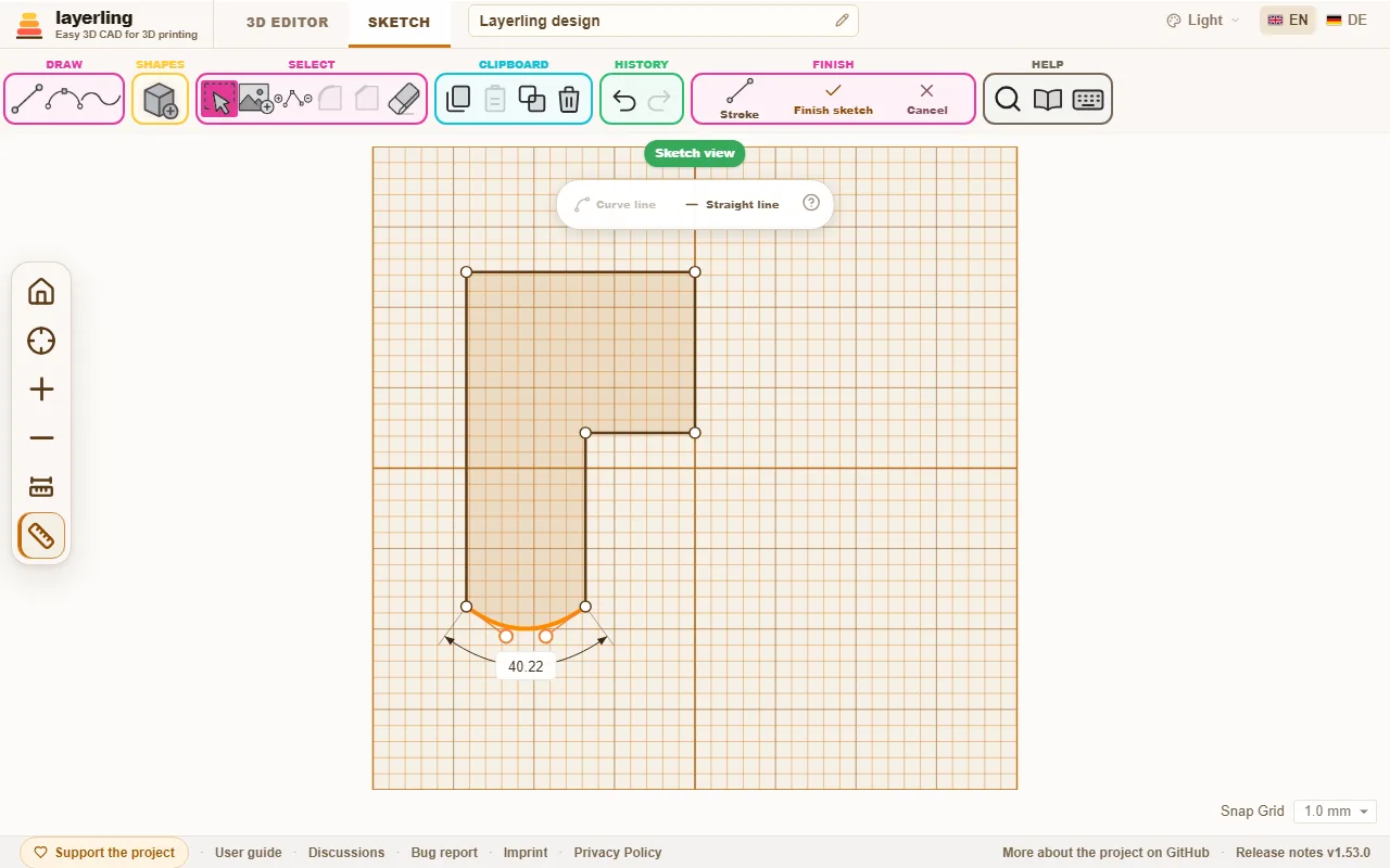
Select a straight line and click “Curve line” in the bar that appears: the side bows out into a curve, as in Tinkercad, and shows its two handles. Drag them to shape the curve; the further out a handle stands, the stronger the bend. “Straight line” makes the side straight again. A point you select can be made round with “Smooth Curve”: it gets handles of its own and the lines next to it become curves.
Reading and typing angles
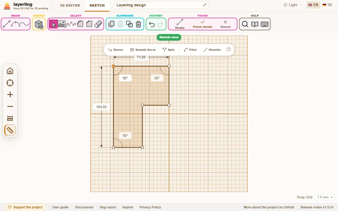
Click a corner point where two straight lines meet: next to the lengths, layerling shows the angle between them in degrees, with a small arc. On a closed outline it is the angle inside the shape, so a dent reads above 180°. Click the value and type a new angle. One of the two lines then turns about the corner and keeps its length, and the other stays where it is. The line that turns is drawn dashed; Tab switches to the other one, Enter applies and Esc cancels. What hangs at the far end of the turned line goes with it.
Moving a point changes three angles: at the point itself and at the two neighbouring corners at the far ends of its lines. So layerling shows those two as well, and each can be clicked and typed. That way you set, say, the bottom left corner to 75.5° while the top left point, which moves for it, is selected. You can calculate here too, e.g. "90-14.5".
A corner shows no angle where a curve meets it, or where more than two lines meet. The “Show measurements” button on the side bar hides the angle together with the lengths.
Rounding or chamfering corners
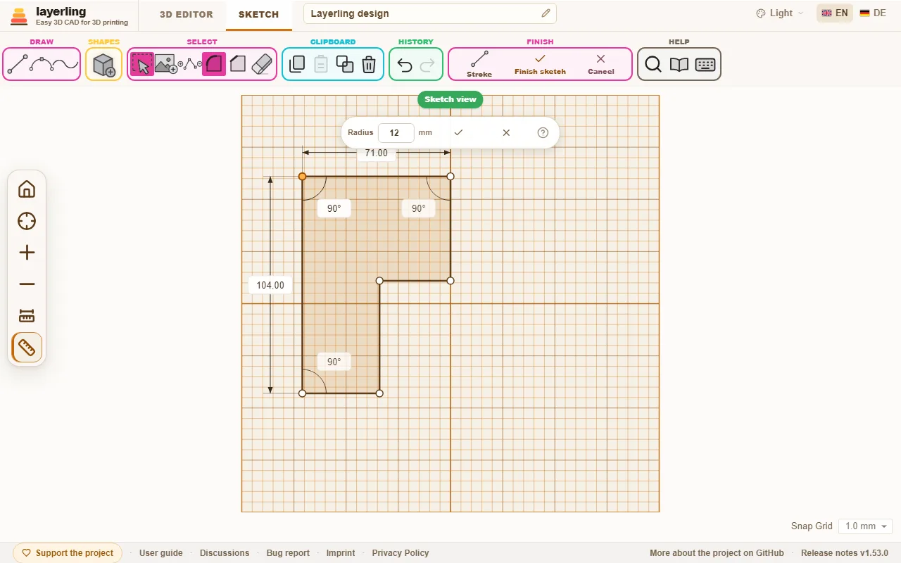
Click a corner point and choose “Fillet corner” or “Chamfer corner”. A small field appears for the “Radius” or the “Distance”. Enter the size and confirm with the check mark. This works for corners between two straight lines.
Several corners at once work too: select them with Shift and a click each, or pull a frame round them, and choose “Fillet corner” or “Chamfer corner” from the bar that appears. All of them get the same radius or distance. Where two selected corners share a side, each takes at most 45 % of it, so a rectangle rounded all round comes out alike at every corner. Points that are not a corner between two straight lines are left out, and the message says how many. A frame round a whole shape, or a click inside it, selects its corners and its lines together, and the bar then offers “Curve line” and “Straight line” for all the selected lines next to the corner tools.
Construction lines
A construction line helps you place points without becoming part of the body. It is drawn dashed and never counts as outline: you can pull it as far beyond the shape as you like and the body does not grow.
- Switch on “Construction line” in the “Draw” group. New lines, those typed by measure too, are then construction lines. The button switches back to normal lines.
- A line you have drawn already becomes a construction line when you click it and choose “Construction”. “Make a line” makes it a normal line again.
- New points snap to where a construction line crosses another line, a blue ring shows it, and to the ends of the construction line. That is how you put a corner on a middle, at a fixed distance from an edge or on a crossing, without calculating.
- A construction line does not cut the outline apart where it crosses it. When revolving it may lie to the right of the axis too.
Making a body from it
Click “Finish sketch”. The outline stands as a body on the workplane. In its settings you change the height, the colour and everything else as with any other shape. When you resize it, layerling builds it again from the sketch a moment later, and the sketch grows with it. So it stays an exact body that takes chamfers and fillets, and the next time you edit it the sketch has the size the body has.
If the workplane lies on the side of a body, you draw the way you look at that side: up in the sketch is up on the finished body too. The faint outline of the body in the sketch view shows where it stands. If the workplane cuts through a body, the sketch view shows the outline of that cut instead, so a hollow body appears as a ring and you can line the sketch up with its walls. A point you set or drag close to a corner of these outlines snaps exactly onto it; a small blue ring shows it. That way you take edges of other bodies into the sketch, even when the workplane does not lie exactly on them.
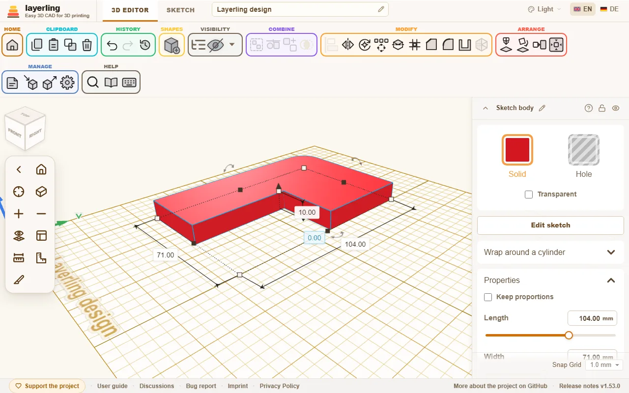
With “Edit sketch” you can return to the sketch at any time to change it. A double click on the body does the same, as in Tinkercad (a locked body stays closed); “Double-click opens the sketch” in the settings switches that off. Edge treatments you already made on the body are lost, though, because the edges are created anew.
Revolving
When revolving, you draw half the cross-section to the left of the axis shown in the sketch. Next to it you see a 3D preview of the revolve. It shows at once what the body will look like. The outline must be closed. At the end click “Finish revolve”.
A revolved body is an exact body, like an extruded one: it takes chamfers and fillets, and you can hollow it, for a cup or a vase. A body revolved with an older layerling is a mesh; open “Edit sketch” and finish it again to make it exact. A profile that reaches across the axis cannot be built exactly and becomes a mesh, as before.
Building as a stroke
Normally the area inside a closed outline becomes the body. With “Stroke” in the “Finish” section you build the line itself instead, with a width you set. Tick “Build as a stroke” in the panel; the sketch shows straight away what comes out.
- A closed outline becomes a frame. “Position” says where the wall lies: “Centred” on the drawn line, “Inside” within it or “Outside” outside it. Outside is handy for a tolerance: draw the outline of a hole, a dovetail for instance, and give it a 0.2 mm stroke outside to get the gap the print needs.
- An open line becomes a stripe, centred on the line. “Ends” sets how its ends look: “Flat”, “Square” (longer by half the width) or “Round”.
- “Corners” applies to both: “Sharp”, “Round” or “Bevel”.
The sketch keeps the drawn line. Open it again and you go on changing line and stroke; untick the box and the area is built again. Curves are broken into short straight pieces for it. A revolve has no stroke.
Fill and silhouette
You can set the stroke without opening the sketch too: in the properties of a sketch body, choose “Area”, “Stroke Outside”, “Stroke Inside” or “Stroke Centred” under “Fill”, with “Line Width” and “Corners”. The body is built again straight away, where it stands. These match the fill modes of Tinkercad's SVG import: default, outer line and inner line. “Wider” keeps the area filled and grows it by the line width all round, with sharp, round or bevelled corners: a base layer under a logo for a multicolour print, which the stroke outside alone would only give as a ring.
“Silhouette (No Holes)” leaves out every outline lying inside another: holes and whatever lies in them. Only the outer outline stays. Together with “Stroke Outside” it makes a cookie cutter: import an SVG twice, once with the silhouette as an area for the base and once with the silhouette and 1 to 2 mm of stroke outside as the wall. The switch is in the “Stroke” panel in sketch mode as well.
Fillets and chamfers on the edges go when the body is built again, as when the sketch is edited.
Slanted walls, for stamps
An extruded sketch has vertical walls. A stamp, an embossing die or a punch wants slanted ones, outside and inside, with the same wall thickness all the way. Layerling has no draft angle for an extrusion, but for plain outlines the “Taper” gets you there. One way that works:
- Draw the outline with the hole it needs and make a body of it. Duplicate the body (Ctrl+D).
- On the first body, switch on “Silhouette (No Holes)”, so the hole is filled, and give it a wider bottom than top with “Taper”.
- On the copy, open its sketch again and delete the outer outline, so that only the outline of the hole is left. Finish the sketch, switch the body to “Hole” and give it a narrower bottom than top with “Taper”.
- Move the hole into the first body, where the hole was, and group the two.
The walls now slope outside and inside. Taper scales the whole outline, so this is exact for plain shapes, where you can choose the sizes so the walls run parallel, and only an approximation for fine details such as lettering.
A picture as template
With “Add Image” you put a photo or a drawing under the sketch and trace it. You can set its size, opacity and position. Once the picture sits right, lock it with L so you do not move it by accident while drawing. A locked image is out of the way: clicks go through it, so you can pick lines and points on top of it and drag a frame over them. To select it again, for example to unlock it, Alt+click it. If its settings at the right edge cover the picture, drag them away by their title bar; a double-click on it docks them again.
Under “Align” you line up a photo that was not taken straight:
- “Rotation”: Turn the picture about its centre, with the round handle above its frame or as a number in degrees. With Shift the handle snaps in 15° steps.
- “To X = 0” and “To Y = 0”: put the picture's centre on X = 0 or Y = 0. For a revolve, X = 0 is the axis, so the picture then lies symmetric about it.
- “Calibrate”: Click two points in the picture whose distance you know, the ends of a ruler or a known diameter, and type the real distance. The picture is scaled evenly so that distance is right; the first point stays where it was.
- “Crop”: The handles on the frame now crop the picture instead of scaling it; what is cut away stays stored and comes back with “Show whole picture” or when a handle is pulled out again.
All four touch the reference only, never the sketch.
Keys in sketch mode
| Key | Effect |
|---|---|
| Esc | end the line chain, clear the selection |
| Delete | delete the selected element |
| Ctrl+C | copy the selection |
| Ctrl+X | cut the selection |
| Ctrl+V | paste |
| Ctrl+D | duplicate the selection |
| Ctrl+Z | undo |
| Shift | while drawing: snap the line in 15° steps; while dragging: keep movement on one axis |
| digit, <, Tab, Enter | while drawing: type and set the length and angle of the next line |
| R | rotate the closed sketch by 45° |
| L | lock or unlock the template image |