
Threads, gears and other parts
Screws, nuts and tapped holes that fit together, plus gear, spring, bent tube, dovetail, teardrop hole, counterbore and countersink.
Ten rozdział nie jest jeszcze przetłumaczony na polski. Poniżej tekst angielski.
Besides the basic shapes, the library contains some parts that would be tedious to put together yourself. All of them can be changed afterwards in their settings.
Threads
Choose „Gwint” in the shape library. Under „Rodzaj” you decide what it should be:
- „Pręt gwintowany”: a cylinder with thread, for example a screw without a head.
- „Śruba”: with a head. You choose the „Łeb”: „Łeb walcowy z gniazdem”, „Łeb stożkowy” or „Łeb sześciokątny”.
- „Nakrętka”: the matching nut.
- „Otwór gwintowany”: a tapped hole. It is a hole. Drag it into a part, group both, and the part has an internal thread.
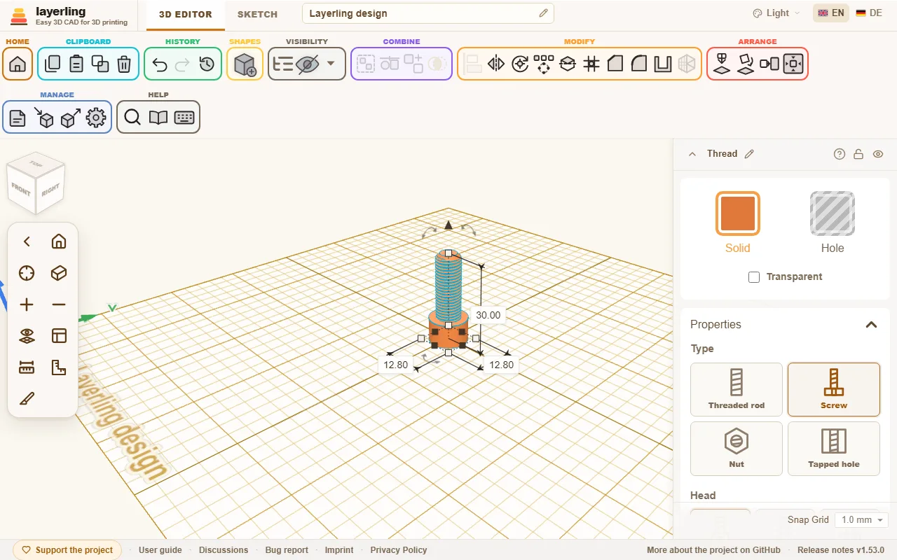
You pick the size under „Rozmiar” from a list: metric from M2 to M12, the inch sizes UNC and UNF from No. 4 to 1 inch, and the pipe threads G1/16 to G4. If you choose „Własny”, you set „Średnica” and „Skok” yourself. For an inch size or a G size the field asks for „Zwoje na cal” instead of the pitch in millimetres.
The list groups the sizes by series, and a line under the field names the series of the size you picked, with examples you know from everyday life:
- M, metric coarse: the ISO metric coarse thread to ISO 261, as on standard screws and nuts.
- UNC, US inch coarse: the camera and tripod screw is 1/4"-20 UNC (ISO 1222), larger tripod heads use 3/8"-16 UNC.
- UNF, US inch fine: the same diameters as UNC with a finer pitch (ASME B1.1).
- G, pipe thread: a shower hose connects with G1/2, a washing-machine inlet hose with G3/4. A garden tap ends in G3/4, smaller taps in G1/2; that is where the tap connector of a click-on hose system screws on.
The G sizes are the parallel Whitworth pipe threads to ISO 228-1, found on fittings for water, gas, hydraulics and pneumatics. The size names the pipe, not the thread: a G1 measures 33.249 mm across the thread. Choosing a G size sets the profile to „Whitworth (55°)”, and choosing a metric or inch size sets it back to „Trójkątny (ISO)”. A „Trapezowy” or „Okrągły” profile you picked yourself stays. The standard only defines the thread, so the head of a screw and a nut on a G size get the same proportions as on a diameter you set yourself. The tapered pipe threads R, Rc and Rp are not included.
More settings:
- „Kierunek”: „Prawy” or „Lewy”.
- „Zarys”: „Trójkątny (ISO)” is the standard profile of metric and inch threads, „Whitworth (55°)” that of the G pipe threads: 55° with rounded crests and roots. „Trapezowy” and „Okrągły” have flat crests and roots. That usually prints more reliably because no thin tips result.
- „Własny (trapez)”: A trapezoid you shape yourself, with a flat crest and a flat root of the same width. „Kąt zarysu” is the angle between the two flanks of a tooth: 60° is the sharp V thread, 30° the trapezoid thread, and at 90° or less no flank is flatter than 45°, so the thread prints without supports. „Głębokość gwintu” and „Średnica rdzenia” are one measure said two ways: the core diameter is the diameter minus twice the depth, and changing one changes the other. A new own profile starts with the V thread's depth at 60°. The depth has limits that depend on the angle and the pitch: not shallower than a tenth of the pitch, not deeper than 40 % of the diameter, and not so deep that the two flanks take more than nine tenths of the pitch. If you change the pitch, the depth follows in proportion; if you scale the thread, so does the depth. The play and the chamfers work as with the other profiles. Through the MCP bridge the profile is
customwiththreadFlankAngleandthreadDepth. - „Luz (XY)”: For nut and tapped hole, the room that makes sure a printed pair really turns. The coarser your printer works, the more clearance the pair needs. It is the extra room across the whole diameter, and the gap between the flanks of a V thread is only about half of it, so a printed pair needs more than you might expect: new nuts start at 0.4 mm, 0.3 is tight and 0.5 loose. Print a test pair first. Rods and screws have a clearance of their own here, which makes the bolt that much thinner in diameter. It is set to 0. Which side gets the room depends on what you pair:
- Printed screw and printed nut: leave the screw at 0 and give the nut the room (the 0.4 mm it starts with).
- Real screw in a printed nut or tapped hole: the printed side takes all of it, so the nut keeps its 0.4 mm. A tighter 0.3 mm is worth a test if the screw wobbles.
- Printed screw in a real nut: the real nut has no play, so the screw has to be thinner: 0.3 to 0.4 mm here, as much as a printed nut would have.
- „Luz wzdłuż osi (Z)”: For nut and tapped hole, the play along the axis, on top of the „Luz (XY)”. Every tooth of the nut gets this much thinner, the diameter stays as it is. The reason: the „Luz (XY)” works on the diameter only and opens the flanks of a V thread to about 0.58 of its value. Anyone who wants air between the flanks has to open the diameter wide and gets sideways slop for it. The play along the axis sets the two apart. It is set to 0, so a saved thread does not change, and it goes up to a fifth of the pitch at most, because above that nothing would be left of the nut's teeth. The field exists for nut and tapped hole only; rod and screw keep their own clearance. More below under "Threads for 3D printing".
- „Fazka, górny koniec”, „Fazka, dolny koniec”, „Fazka łba” and „Fazka obrzeża”: Chamfers at the ends so the thread starts cleanly and the head has no sharp edge. Each end of a rod, nut or tapped hole has its own chamfer, so the top can be long and the bottom short or none. A screw has only one at its tip, labelled „Fazka”. On a nut or tapped hole the chamfer is the room the mouth opens beyond the outer diameter; the cone runs at 45 degrees on down to the thread core, so no ledge is left at the outer diameter.
Switching a thread between „Pręt gwintowany” and „Otwór gwintowany” keeps its length. A nut and a screw start from their standard measures.
- „Jakość”: How finely the thread is calculated. Higher is more exact, but slower.
Printed threads are a topic of their own. Make the screw-and-nut pair as a test first before you print a large part, and adjust the clearance to your printer.
Threads for 3D printing
A printed thread needs air in two places, and they act differently:
- Clearance in the diameter („Luz (XY)”): makes the nut wider. The screw then has half the value as air on each side, 0.2 mm at 0.4 mm. The thread turns easily, but the screw can wobble sideways.
- Play along the axis („Luz wzdłuż osi (Z)”): makes the teeth of the nut thinner. The screw can then move back and forth along the axis by that value when it is not tightened. There is no extra air to the side for it.
Together they make the gap between the flanks: about 0.58 times the clearance in the diameter plus the play along the axis. An example for a 0.3 mm gap: it used to take 0.5 mm in the diameter, that is 0.25 mm of air on each side. Now 0.2 mm in the diameter (0.1 mm on each side) and 0.2 mm along the axis do it, and the gap is 0.32 mm.
Consequences to know
- The screw has play along the axis. Without load it can move back and forth by that value. For fastenings, lids and housings that does not matter; for a lead screw that has to position exactly it does, so keep it small or at 0 there.
- The nut's teeth get thinner. With 0.3 mm at a pitch of 1.75 mm every tooth is almost a third thinner at its middle and so clearly less strong. For heavily loaded parts take a coarser thread instead.
- More to calculate. The tooth shape gets extra points, so the thread has more triangles and takes a little longer to compute.
- No true arc in the STEP export for the Whitworth profile. A „Whitworth (55°)” thread with play along the axis goes to the edge tool and the STEP export as a tooth shape made of straight pieces, not with the true circular arcs. At 0 everything stays as before.
Tips
- A test pair first. A screw and a nut, each only 4 to 6 mm tall, take a few minutes. Print three pairs with different play side by side and take the one that turns easily and does not wobble.
- Start with values that often fit. Clearance in the diameter 0.2 to 0.3 mm and play along the axis 0.2 mm. If the screw wobbles sideways, lower the clearance in the diameter; if it jams, raise the play along the axis. If you would rather do without the play along the axis, use 0.4 mm in the diameter as before.
- The play along the axis should be at least one layer height. What lies below one layer the printer does not resolve. With a layer height of 0.2 mm, 0.2 mm is a good start; with 0.1 mm, less is enough.
- Print screw and nut upright. The axis points up, so every turn lies in whole layers and the flanks come out clean. Lying down, the flanks sag.
- Fine pitches are hard. Below about 1 mm of pitch the turns often fuse. A coarser thread, or a „Trapezowy” profile with flat crests, prints more reliably than a fine V thread.
- Avoid thin tips. The V thread has a narrow tip that the printer hardly hits with its nozzle width. The „Trapezowy” and „Okrągły” profiles have flatter teeth.
- Deburr and run it in. The first turns are often stiff because small remains of the print stand on the flanks. Turn it back and forth a few times and it runs easier. The chamfer at the start helps threading it in.
- Another printer or filament. The play depends on the printer, the material and the nozzle. Print the test pair again when you change either.
The edge tool takes a thread as its exact body. You can chamfer or round the part that carries it with the thread already in place, or the rims of a screw head, see Breaking edges and hollowing bodies. Working out a thread's edges takes a while: a few seconds for an M6, about half a minute for a G1/2 pipe thread. The quickest way to break the edge of a screw head is still the head chamfer in the properties.
Gears
„Koło zębate” comes as „Koło walcowe o zębach prostych”, „Koło walcowe o zębach skośnych”, „Koło daszkowe” and „Koło stożkowe”, and as „Wieniec zębaty” and „Zębatka” (further down). New gears have „Ewolwentowy” under „Kształt zęba”: teeth with involute flanks, as gear generators and engineering use them. Such teeth roll cleanly on each other. You set the number of „Zęby” and the „Moduł (mm)”, and the size follows: the outside diameter is module × (teeth + 2), the pitch circle module × teeth. New gears start at module 2. Two gears mesh when they have the same module and the same „Kąt przyporu” (usually 20°) and their centres stand (teeth + teeth) × module / 2 apart. Select both gears and the properties panel gives that centre distance and how far apart the centres are now. If a tooth then meets a tooth instead of a gap, turn one of the gears by half a tooth, which is 180° divided by its number of teeth. „Luz międzyzębny” takes a little off the teeth so a printed pair does not bind. The value is for the pair, and each gear takes half of it; 0.2 mm is a good start, 0 gives the exact gear. Below the base circle the flank runs straight down to the root and is not undercut as a cutter would do it. That suits printing, but a very small pinion below about 17 teeth may rub slightly at the root.
A helical gear adds the „Kąt pochylenia linii zęba”. With involute teeth it is the true helix angle on the pitch circle: two helical gears mesh when they have the same module and the same angle, one positive and the other negative. The „Koło daszkowe” is two helical halves turning opposite ways: the teeth run one way up to half the height and back after it, like an arrow. That has two advantages for 3D printing: the gear centres itself on its shaft, and it has no axial thrust, because the forces of the two halves cancel. A helical gear, in contrast, pushes sideways along its axis. You set the „Kąt pochylenia linii zęba” and the „Jakość linii śrubowej” as for the helical gear; the angle applies to each half. Two herringbone gears mesh when they have the same module and the same angle with opposite signs, one positive and the other negative. There is no groove in the middle, as on milled herringbone gears: the two halves run into each other without a step. The edge tool and the STEP export take the herringbone gear as a triangle mesh, not as an exact body.
The bevel gear takes the involute teeth and makes them smaller towards its top. That is an approximation, not an exactly worked out bevel pair.
„Okrągły” are round teeth made of arcs, like Tinkercad's Useful gear: tip and gap run into each other without a corner. Small gears print more forgivingly that way and turn more easily, and on a knob the teeth make a pleasant grip. Round teeth are set by „Zęby”, „Moduł (mm)” and „Luz międzyzębny” too; they have no pressure angle. They stand lower than involute teeth, so the outside diameter is module × (teeth + 1.2). Round gears with the same module mesh, at the same centre distance as involute ones; with an involute gear they do not fit.
„Prosty” are the straight teeth every gear had so far. There you set „Rozmiar zęba” and „Szerokość zęba” by hand. Older designs keep them until you change the tooth shape. All three tooth shapes have the „Otwór środkowy”.
The „Wieniec zębaty” has its teeth pointing in: a ring that a smaller gear runs inside, like the outer wheel of a planetary set. You set it like an involute or round gear by „Zęby”, „Moduł (mm)” and „Luz międzyzębny”, plus the „Wieniec”, the ring outside the teeth. Its outside diameter is module × (teeth + 2.5) plus twice the rim, with round teeth module × (teeth + 1.7). A gear of the same module runs in it when its centre stands (ring teeth − its teeth) × module / 2 from the ring's centre; select both and the properties panel gives that distance. For a planetary set, ring teeth = sun teeth + 2 × planet teeth, for example 30 = 12 + 2 × 9. A ring gear has no centre hole, it is the ring itself. Between 26 and 33 teeth its tips are up to a quarter module shorter, because a tiny edge would otherwise form at the base circle; meshing is not affected.
The „Zębatka” is the gear of endless radius: a bar with teeth along one side, whose flanks are straight lines at the pressure angle with involute teeth. Its width (along X) is teeth × pitch, the pitch being π × module, so racks of one module line up end to end, each end falling in a gap. Its length (along Y) is the thickness of the bar and free, as long as the teeth and half a millimetre of bar fit in. The teeth point to the front, towards the viewer of the home view; turn the rack as you need it. A gear of the same module rolls on it when its centre stands its teeth × module / 2 in front of the pitch line; the pitch line lies a module behind the tooth tips, 0.6 module with round teeth. Ring gear and rack come with involute and with round teeth, not with simple ones; switching the gear type keeps the module.
The edge tool and the STEP export take every gear as its exact body, involute flanks as smooth curves. A helical gear on an oval footprint stays a triangle mesh, and so does a helical gear with involute teeth from about 31 teeth. Small teeth limit how far edges can be rounded: on a gear with simple teeth, 30 mm across with 12 teeth the flat between two teeth at the foot is only about 0.65 mm wide, so rounding every edge works up to about 0.5 mm, and on a bevel gear, whose top is smaller, up to about 0.4 mm. A helical gear's teeth lean, which narrows that flat across its slanted edges: the larger the helix angle against the gear's height, the smaller the rounding that fits. The edges of its two flat ends can be rounded, but chamfering just those edges fails in the CAD kernel; round them, or chamfer all edges together at a smaller size, such as 0.2 mm.
Springs
The „Sprężyna” has „Zwoje” and a „Drut”. Together with the height they decide how soft the spring is. „Kierunek zwijania” sets which way the wire runs: „Prawoskrętna” like a usual compression spring, or „Lewoskrętna”.
The edge tool and the STEP export take a spring as its exact body: a round wire along a helix, cut square at both ends. You can round or chamfer those two wire ends, for instance.
Bent tubes
A „Wygięta rura” consists of up to twelve sections: a straight piece followed by a bend. For each you set the „Długość prosta”, the „Kąt gięcia”, the „Promień gięcia” and the „Kąt obrotu wokół osi”. The section you are editing is lit up in orange on the tube, so you can follow the order. A roll angle of 0° bends within the plane of the workplane, at 90° the tube bends upward. The profile can be round, square, hexagonal or octagonal, the inside likewise, or fully solid. If the tube runs into itself, layerling warns you.
Loft
The „Przejście profili” joins one outline at the bottom to another at the top, like a loft in Fusion: a hose adapter from one diameter to another, a square fan onto a round duct, a stand that turns round towards the top. For each end you pick „Kontur dolny” and „Kontur górny”: „Okrąg / elipsa”, „Prostokąt” with „Promień narożników dolnych”, or „Wielokąt” with its number of corners, plus the width and length of each end and the height. „Przesunięcie góry wzdłuż szerokości” and „Przesunięcie góry wzdłuż długości” move the top end sideways for a slanted transition; the bottom end stays where it is.
„Grubość ścianki (0 = pełna)” turns the solid body into a tube open at the top and the bottom. The opening is smaller by the wall at both ends, measured across; where the wall slants it is a little thinner. Drag the frame bigger and both ends grow along, while the corner radius and the wall keep their size.
„Płynne przejście (%)” makes the transition smooth. At 0 the sides run straight from the bottom to the top, as on a cone. At 100 they leave both ends straight up and change their size in between along an S-curve: a hose adapter that flares smoothly from a narrow to a wide pipe, instead of running like a funnel. In between the slider mixes the two. A smooth transition works together with „Grubość ścianki (0 = pełna)”, a twist, a tilt and a sideways offset; a tube with a wall stays open at both ends. It is an exact body like the straight one, so its edges can be chamfered and filleted, but it is built through several sections and takes a little longer to calculate.
„Skręt” turns the section evenly about the vertical on the way up, up to 360° either way; the sides then wind round. „Pochylenie góry, przód/tył” and „Pochylenie góry, lewo/prawo” tilt the top end, up to 45°: a positive value raises its front edge or its right side. The sections in between tilt by their share, so the wall runs smoothly into the slant. The highest point stays at the set height. If the height later becomes so small that the slanted end would reach under the plate, the tilt gives way until it fits. A bend along a path, such as a pipe elbow, is not something the loft does.
The loft is an exact body, twisted and tilted too: its edges can be chamfered and filleted, and STEP export keeps it. Add a flange with screw holes as usual and group them.
Hinge
The „Zawias” prints in one piece and moves afterwards (print-in-place): two leaves lying open flat on the plate, with alternating knuckles on one axis between them. The pin belongs to the back leaf and runs with play through the knuckles of the front one. You set the „Długość (oś)”, the „Szerokość po otwarciu” and the „Średnica tulei”, plus the number of „Tuleje” (odd, so the pin is held at both ends), the „Średnica sworznia” and the „Grubość skrzydełka”.
„Luz” is the gap between the moving parts: around the pin, between the knuckles and in front of the leaves. With 0.4 mm a well-tuned printer usually breaks free with a small twist; if the parts fuse, raise it, if it wobbles too much, lower it. Print the hinge lying down as it appears on the plate, without supports. You can add holes to the leaves or group them into a larger part, such as a lid.
Knurling
The „Radełko” is a round grip with grooves all around, for knobs, thumb wheels and tool handles. Under „Wzór” you pick „Proste”, grooves along the axis as on a control knob, „Krzyżowe”: two slanted rows of grooves cross into small diamonds, or „Okrągłe”: grooves and ridges along the axis as a soft wave of arcs, a pleasant grip without sharp ridges. Round grooves stay shallower than half a pitch, or the ridges would bulge at their foot; a depth too great gives way. You set the „Średnica” and the „Wysokość”, the number of „Rowki” and the „Głębokość rowka”; for crossed knurling also the „Kąt rowka” to the axis. The „Fazka na końcach” breaks both ends at 45 degrees, as on a turned knob; 0 leaves them sharp.
Straight and round knurling are exact bodies, so their edges can be broken and rounded. Crossed knurling stays a mesh, because as an exact body it would take almost a minute to compute with 30 grooves. For a knob on a shaft, group the knurl with a hole, such as a „Gwint” set as a tapped hole. Grooves shallower than 0.4 mm hardly any printer prints cleanly, and layerling does not set them closer than 0.8 mm around the grip: a thin grip gets fewer of them.
Dovetail
The „Jaskółczy ogon” is the joint in which two parts lock into each other and can only be slid together sideways. You set the width at the wide end, the „Szerokość szyjki” and the length of the tail. Copy the tail for the other side and make the copy a hole: „Luz jako otwór” then gives a little play so the joint does not jam after printing.
Teardrop hole
A hole lying on its side gets a bridge across its top when printed, and the bridge sags. The „Otwór łezkowy” therefore has a point on top: every layer rests on the one below, and the hole comes out round enough without supports. Set the „Średnica (część okrągła)” to the size of the hole, about 3.4 mm for an M3 screw, and the „Długość otworu” long enough to reach through the part. The „Kąt czubka” is 90°, so the flanks meet at 45°. Most printers handle that cleanly; a flatter point needs more height, a steeper one saves it.
Make the teardrop a hole and group it with the part. Its length runs along the depth and the point faces up. For a hole in the other direction, turn it by 90° around the vertical axis.
A tapped hole on its side sags at the top in the same way. Give it a teardrop of its own: add a „Otwór łezkowy” hole whose „Średnica (część okrągła)” is the core of the thread, the diameter its teeth leave free (about 8.4 mm for M10), the same length as the tapped hole, and select both. Click „Wyrównaj” and bring them into line in the middle - the middle of the teardrop is the middle of its round part, not of its box with the tip, so the two circles lie on each other - and group both with the part. The thread is cut as usual and the tip opens the top of the hole, so it prints without supports.
Counterbore and countersink
A screw head often should not stand proud. The „Pogłębienie walcowe” cuts a round pocket for a socket-head screw (DIN 912), the „Pogłębienie stożkowe” a cone for a countersunk screw (DIN 7991). Both stand with the head end up: the „Średnica łba” is the diameter of the pocket or the cone, the „Średnica trzpienia” the bore below it, the „Długość całkowita” the whole length. On the counterbore you set the „Głębokość łba”, on the countersink the „Kąt stożka” (90° suits countersunk screws). The defaults fit an M3 screw.
Make the shape a hole and group it with the part. Let its top end a little above the surface the head should sit on, so the pocket opens cleanly. For the pocket of a hex nut, use a „Wielokąt” with six sides as a hole.